The track is Peco 100 flexible track, the only available standard when we began our layout more than 40 years ago, and will accommodate both vintage and modern wheels. We used PVE adhesive to glue the track to a cork base, which is itself, stuck onto insulation board sheets (now virtually impossible to obtain.) Originally, we chose to convert our points and crossovers to live frog, as Peco did not produce live frog turnouts at that time. God was definitely on our side when ‘Peco’ later produced their own live frog system.
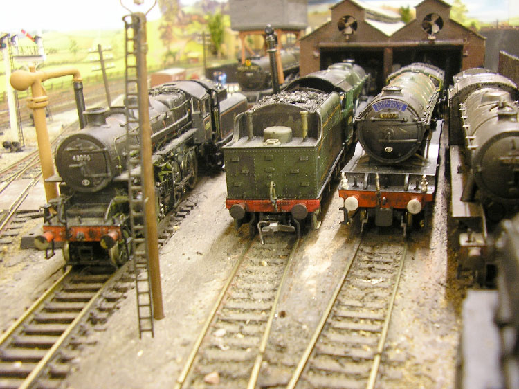
ISOLATING TRACK SECTIONS AT ELTON ROAD SHED
Hornby Central is operated on a common return basis. ie one side of the entire track is negative. Power is turned on and off to the different sections ie the positive side of the track, on which you want the locomotive to run. The points also assist with isolating track sections and sidings, giving more flexibility to the operation. Care has to be taken, as a negative can meet up with a positive under certain track plans. A simple rule of thumb is to always feed power into a point from the toe end. If we were starting again we might well consider digital control, but analogue was well established long before this system was developed.
Control is obtained via three controllers, although the layout can be operated by only two people. The oval layout is divided down the middle, with each controller operating the points and signals on its side of the layout. One controls Hornby Station and depot, the second controls Elton Road and its shunting yard and engine shed. Trains are run around the entire circuit by each controller powering the sections on which the train needs to run. If both controllers feed the same section then a cut out saves the circuit.
The Hornby Central controller can, therefore, depart a train and power it all around the track, but he can only operate the points and signals in his own section, and needs the right of way from the second controller, before he can enter the tracks through Elton Road. This controller might be shunting on the same tracks, or he has a delay to the schedule and has a late departure on his hands. Of course we talk to each other but watching the signals for the right of way adds to the fun and the realism of our running session.
A third person can be given control of the outside slow line without interfering with the two mainline tracks. Our slow line is used for suburban trains, DMUs, goods trains and specials. Hence we can operate three trains at the same time – this is enough when points and signals have to be obeyed.
Trains run on 12 volts DC. Signals, lights and points operate on 16 volts AC.
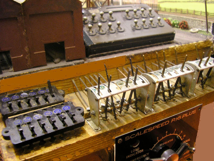
ELTON ROAD SWITCHES AND SIGNAL FRAME
When we first started modelling, even electric points were a novelty. The points on our first section of track, which is Elton Road shed, are operated by rod and wire, with mini pull handles, just like those in the signal boxes at the time. This for us is true nostalgia. We also searched the junk shops for switch boxes, those straight out of Lancaster bombers were the best. They are still doing sterling service, not dropping bombs, just igniting our imagination!
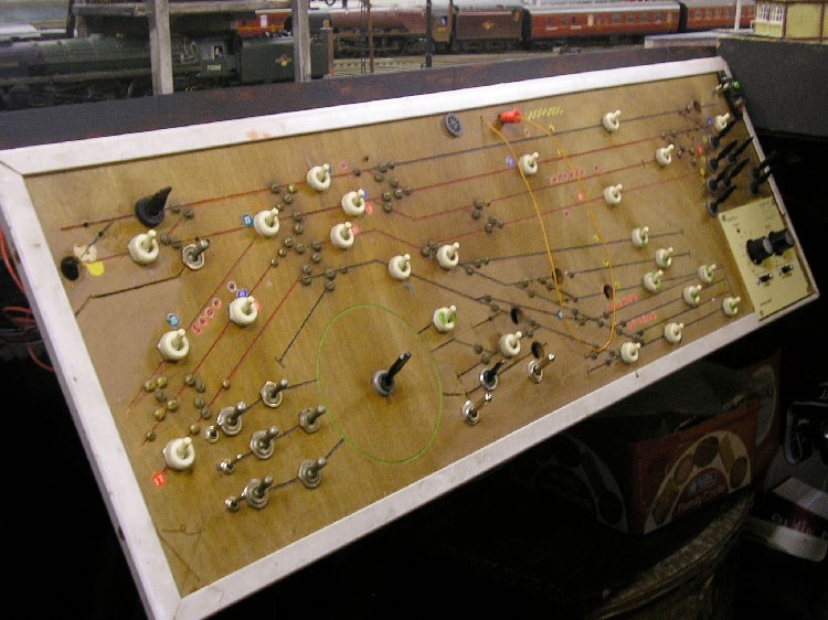
HORNBY CENTRAL TRACK PANEL
By the time we got to powering Hornby Central, track plans were all the rage, so Hornby Central is a doddle to operate compared to Elton Road. We simply run an electric pencil along the path of the train and the track is set. No more learning section numbers; gone is the need to remember point numbers; gone is the necessity to turn off sections we don’t need, which is as important as turning sections on, because if two controllers feed the same section, the train suddenly stops, spilling cups of tea in the restaurant cars and knocking travel bags off the overhead racks!
We hope this has entertained you and increased your interest in modelling a railway.
Hey, don’t forget to turn off the power when your shift is done!